In the void loop(), we first read the potentiometer’s value with analogRead(). Read potentiometer and choose a mode void loop() By calling this function, instead of 3 redundant lines, you just have one line, which is digitalWriteRGB() with 3 parameters.
ARDUINO RGB LED MODULE CODE
This function will help us reduce the code we write in the following.Įvery time you need to change the color of the RGB LED, you will need to call digitalWrite() 3 times. digitalWriteRGB() function void digitalWriteRGB(byte red, byte blue, byte green) Nothing to do for the potentiometer, as an analog pin is already in input mode by default. In the void setup(), we initialize all LEDs (in fact, the 3 legs of the RGB LED) to OUTPUT mode. One for the potentiometer, and one for each color of the LED – we write the code as if we were controlling 3 different LEDs. Setup RGB and potentiometer pins #define RGB_RED_PIN 11Īt first, as a best practice, we create a define for each pin we are going to use. Int mode = map(potentiometerValue, 0, 1023, 0, 6) Int potentiometerValue = analogRead(POTENTIOMETER_PIN) Void digitalWriteRGB(byte red, byte blue, byte green)

We are going to use digitalWrite() – LED fully powered on/off, which means that we have a combination of 7 colors: You can see the RGB LED as a combination of 3 different LEDs that you control separately. In this first application, we are going to modify the color of the RGB LED when we turn the potentiometer knob.
ARDUINO RGB LED MODULE HOW TO
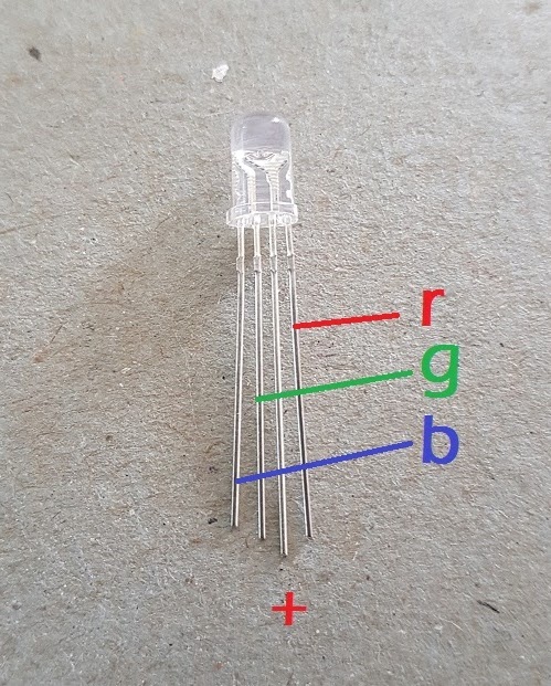
How to find out? Simply check the manual or description of what you’ve bought. Depending on your RGB LED, this can be a cathode or an anode. Make a common ground by connecting a GND pin of the Arduino, to the “minus” line of the breadboard.You are learning how to use Arduino to build your own projects?Ĭheck out Arduino For Beginners and learn step by step. Arduino board – I use Arduino Uno, but any board where you have at least 3 PWM compatible digital pins, and one analog pin, is fine.Going further with the potentiometer and RGB LEDĪrduino circuit with RGB LED and potentiometer.Select a different color for each value.Control the RGB LED with potentiometer – analogWrite() – 1536 colors.Power on the RGB LED depending on the potentiometer’s value.Control the RGB LED with the potentiometer – digitalWrite() – 7 colors.Arduino circuit with RGB LED and potentiometer.Hope that you liked this project and if so then please try to make it on your own. PinMode(4,HIGH) // Red Led Connected To D2 PinĬode for common Cathode // TECHATRONIC.COM PinMode(5,HIGH) // Green Led Pin Connected To D1 Pin PinMode(16,HIGH) // Blue led Pin Connected To D0 Pin Also, make sure that you have uploaded the correct code as per the circuit that you have made.

NOTE: Please upload the code which is given below to the nodemcu as it is. After completing the circuit successfully upload the code which is given below. You can use a breadboard for holding the LED upright.


 0 kommentar(er)
